Ups System Circuit Diagram. Web automatic inverter / ups system connection & wiring circuit diagram. How to connect a ups / inverter to the home supply system? Why & where we need auto ups / inverter system? Web an apc ups (uninterruptible power supply) circuit diagram is a schematic representation of the electrical. The inverter, the battery, and the ac mains. Working principle & operation of automatic ups / inverter. Both the dpdt relays are powered from a 12 v ac to dc power supply or adapter. Introduction to automatic inverter / ups wiring. Introduction to automatic inverter / ups wiring Web the uninterrupted power supply (ups) systems are broadly classified into the following three types −. Web at its core, the ups circuit diagram consists of three main components: Here we can see that the main ups changeover function is carried out by a couple of dpdt relay stages. Web the circuit drawn pertains to a regular industrial ups (uninterruptible power supply), which shows how the batteries take control. The mentioned functional stages of an uninterruptible power supply unit could be understood in detail through the following block diagram:
from schematiclibmesquit77.z21.web.core.windows.net
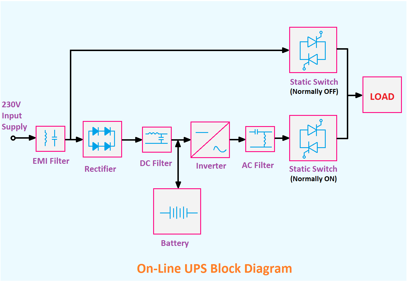
Web automatic inverter / ups system connection & wiring circuit diagram. The mentioned functional stages of an uninterruptible power supply unit could be understood in detail through the following block diagram: Web at its core, the ups circuit diagram consists of three main components: Introduction to automatic inverter / ups wiring The inverter, the battery, and the ac mains. Web an apc ups (uninterruptible power supply) circuit diagram is a schematic representation of the electrical. Working principle & operation of automatic ups / inverter. Introduction to automatic inverter / ups wiring. Here we can see that the main ups changeover function is carried out by a couple of dpdt relay stages. Both the dpdt relays are powered from a 12 v ac to dc power supply or adapter.
Line Diagram Of Ups
Ups System Circuit Diagram Web automatic inverter / ups system connection & wiring circuit diagram. Web the uninterrupted power supply (ups) systems are broadly classified into the following three types −. Working principle & operation of automatic ups / inverter. Web automatic inverter / ups system connection & wiring circuit diagram. Introduction to automatic inverter / ups wiring Web the circuit drawn pertains to a regular industrial ups (uninterruptible power supply), which shows how the batteries take control. Introduction to automatic inverter / ups wiring. Here we can see that the main ups changeover function is carried out by a couple of dpdt relay stages. Web an apc ups (uninterruptible power supply) circuit diagram is a schematic representation of the electrical. How to connect a ups / inverter to the home supply system? The mentioned functional stages of an uninterruptible power supply unit could be understood in detail through the following block diagram: Web at its core, the ups circuit diagram consists of three main components: Both the dpdt relays are powered from a 12 v ac to dc power supply or adapter. The inverter, the battery, and the ac mains. Why & where we need auto ups / inverter system?